Custom GBA Handheld
2026-05-13
Status (updated): Completed — May 30th 2026
I really like handheld stuff! Me and my wife are always in the same ambient doing our stuff. Be it work or our hobbies. You have no idea how many monsters were hunted in monster hunter rise in my OLED switch in its handheld mode! Although I really like my switch and still want to buy myself a steamdeck, I think they're both too big to carry around. Another thing is that I wanted a device that not only could fit in my pocket but also could run my and other pico8 games that I like! I never had a Game Boy Advance, so I thought, hey, why not?! I do like electronics, and buying one ready felt less interesting than building one. I could unite both of my interests: GameDev and Electronics!
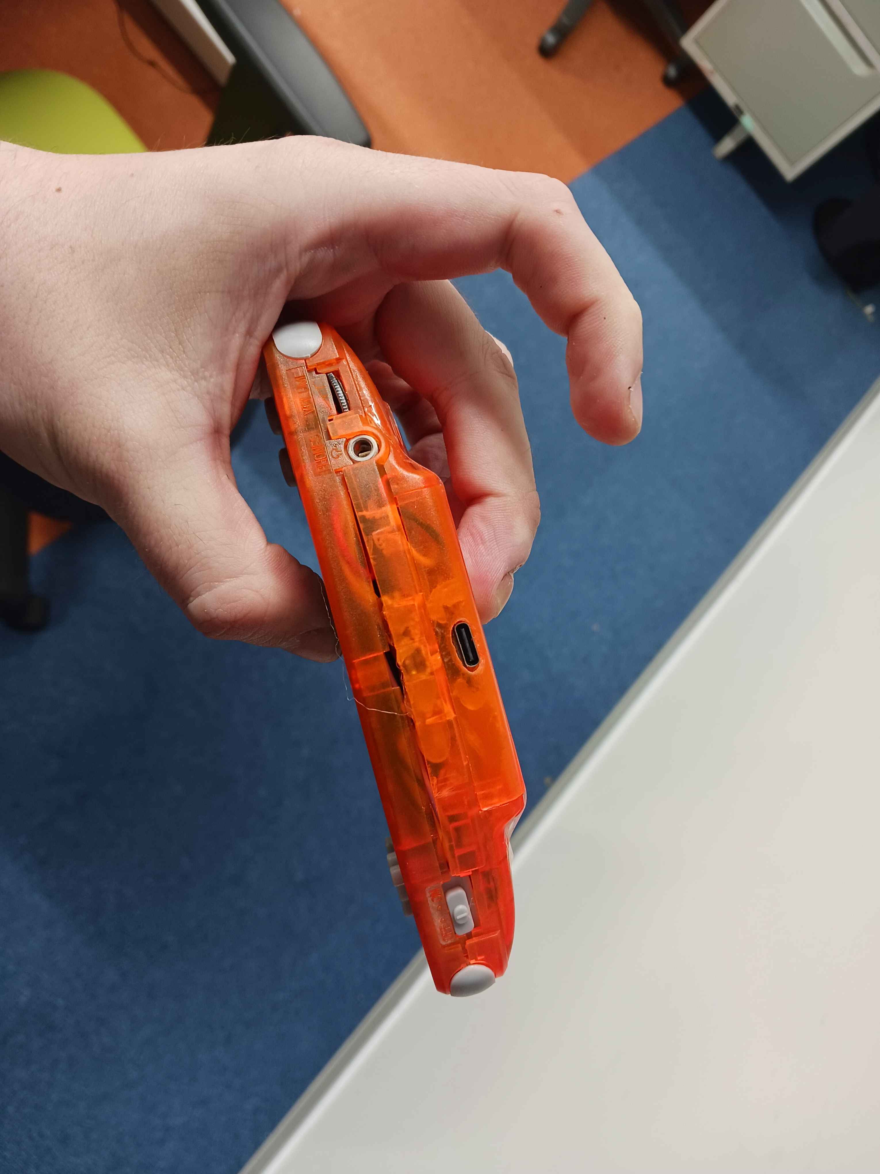
The challenge: fitting a raspberry pi, a 2.8inch display, GPIO input handling, an audio amplifier inside a shell designed for 2001 hardware without the original PCB, without a kit, just components wired together! Oh yes, there's also the battery!
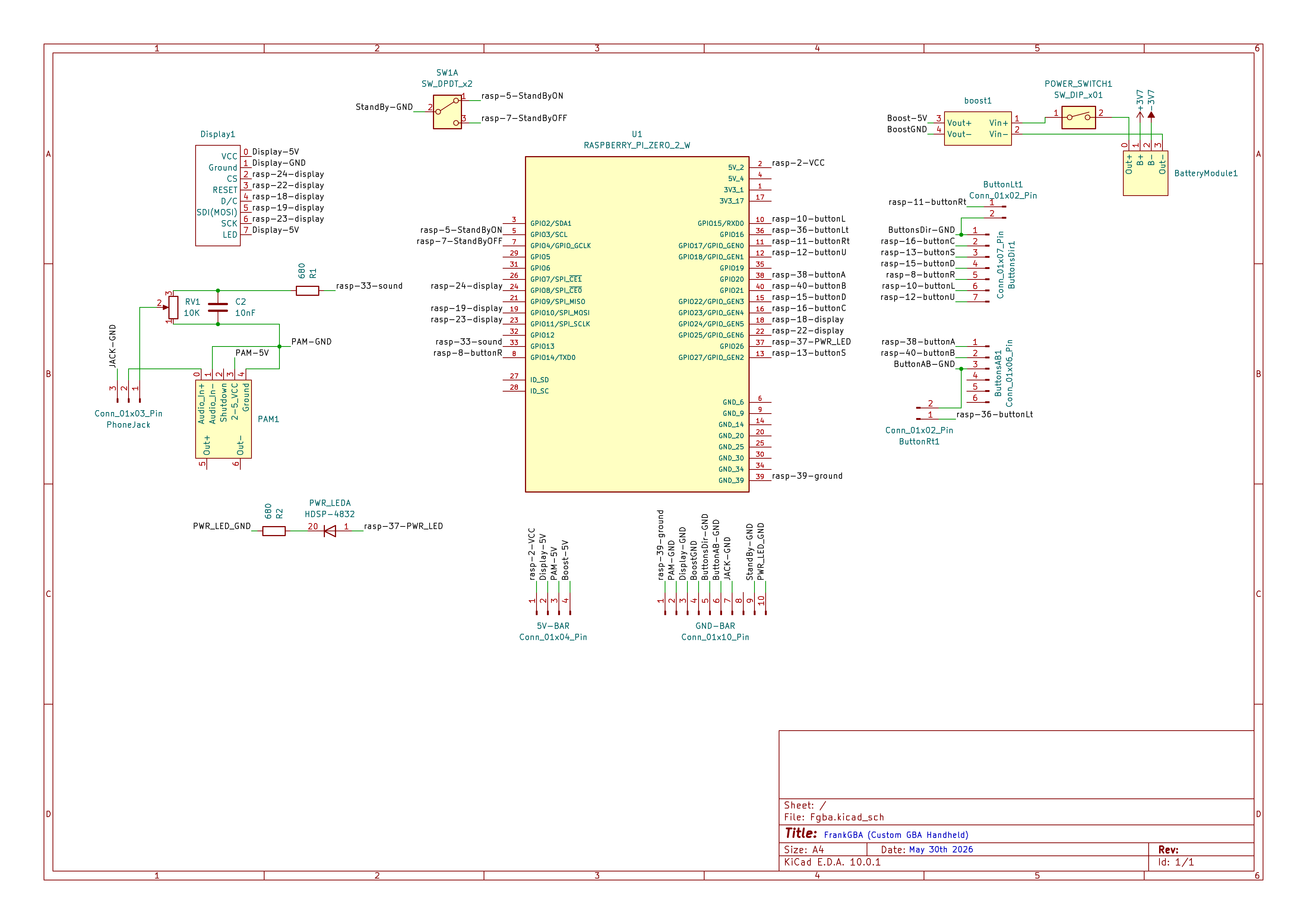
System
| Component | Part |
|---|---|
| Computer | Raspberry Pi Zero 2 W |
| OS | RetroPie |
| Display (Driver) | ST7789 2.8" SPI TFT (fbcp-ili9341) |
| Input | GPIOnext (GPIO buttons) |
| Audio | PAM8302A amplifier |
| Shell | Original GBA case (modified) |
| Battery | 2000mAh Li-Po |
| Battery Charger | Mini 18650 TP4056 Lithium Battery Charger |
| DC-DC Converter | Boost Power Supply Module (winova) |
Display
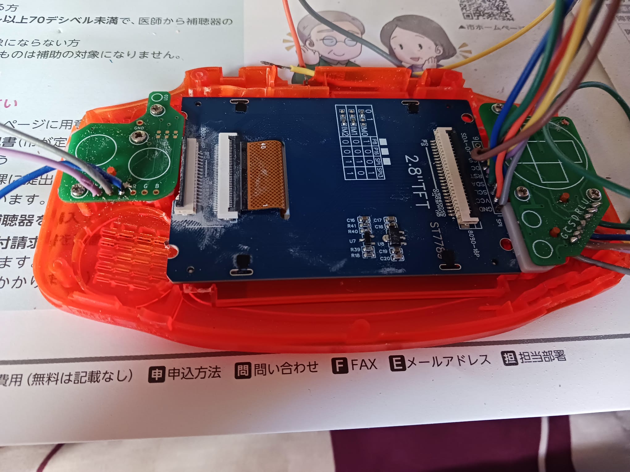
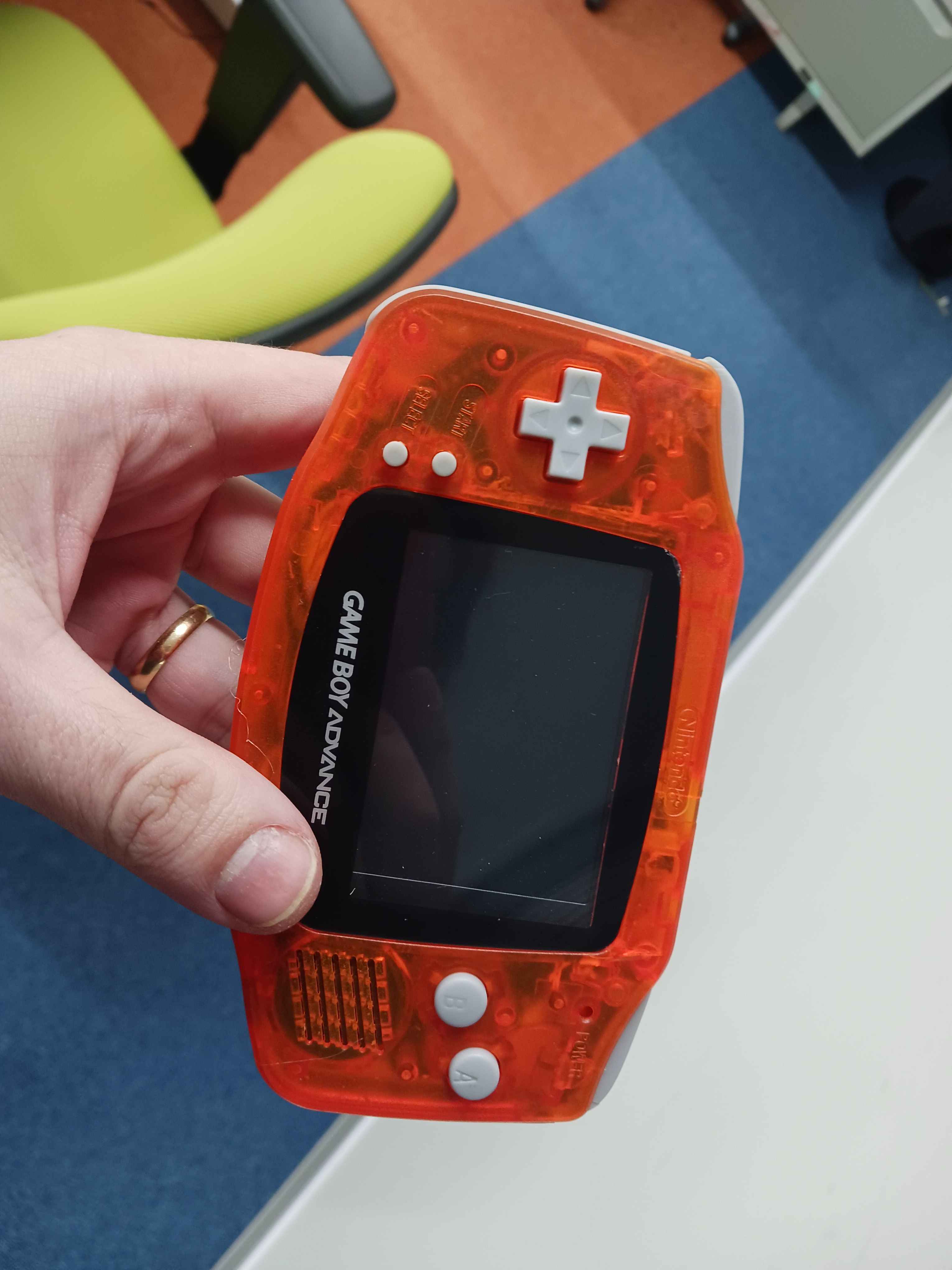
The first display I tried was an ILI9341. It worked! I got RetroPie running on it and was able to play Celeste on PICO-8. But the screen cracked while I was trying to adapt it do the GBA shell since it didn't fit cleanly inside even with physical modifications to the case. I replaced it with a ST7789 2.8" TFT, which fit the shell window much better.
Both displays use the same driver: fbcp-ili9341. Setting it up requires compiling from source with the correct GPIO pin mappings for the specific wiring. The BCM pin numbering used by the driver doesn't match the physical pin numbers on the header, which caused some initial confusion. One issue I hit: after compilation the display was showing inverted colors. Looking at the driver's documentation, this is a known quirk for certain panels and is handled by a compile flag. My final cmake command was:
cmake -DST7789=ON -DGPIO_TFT_DATA_CONTROL=24 -DGPIO_TFT_RESET_PIN=25 -DSPI_BUS_CLOCK_DIVISOR=8 -DDISPLAY_INVERT_COLORS=ON -DSTATISTICS=0 ..
Another thing I had to deal is due to how the display fit inside the shell I had to invert its image inside raspberry's boot config. This line inside the archive solved it:
display_rotate=2
Input
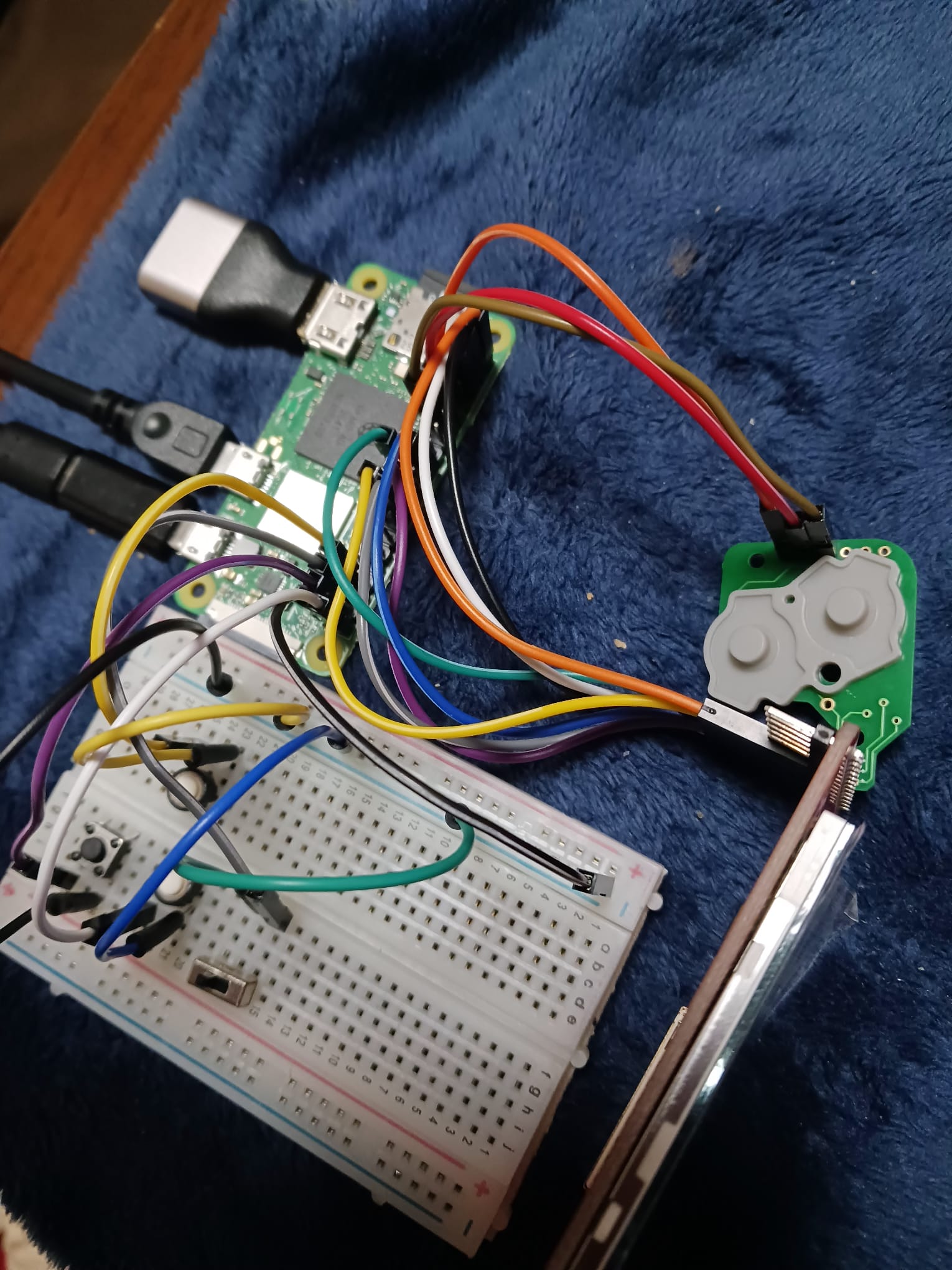
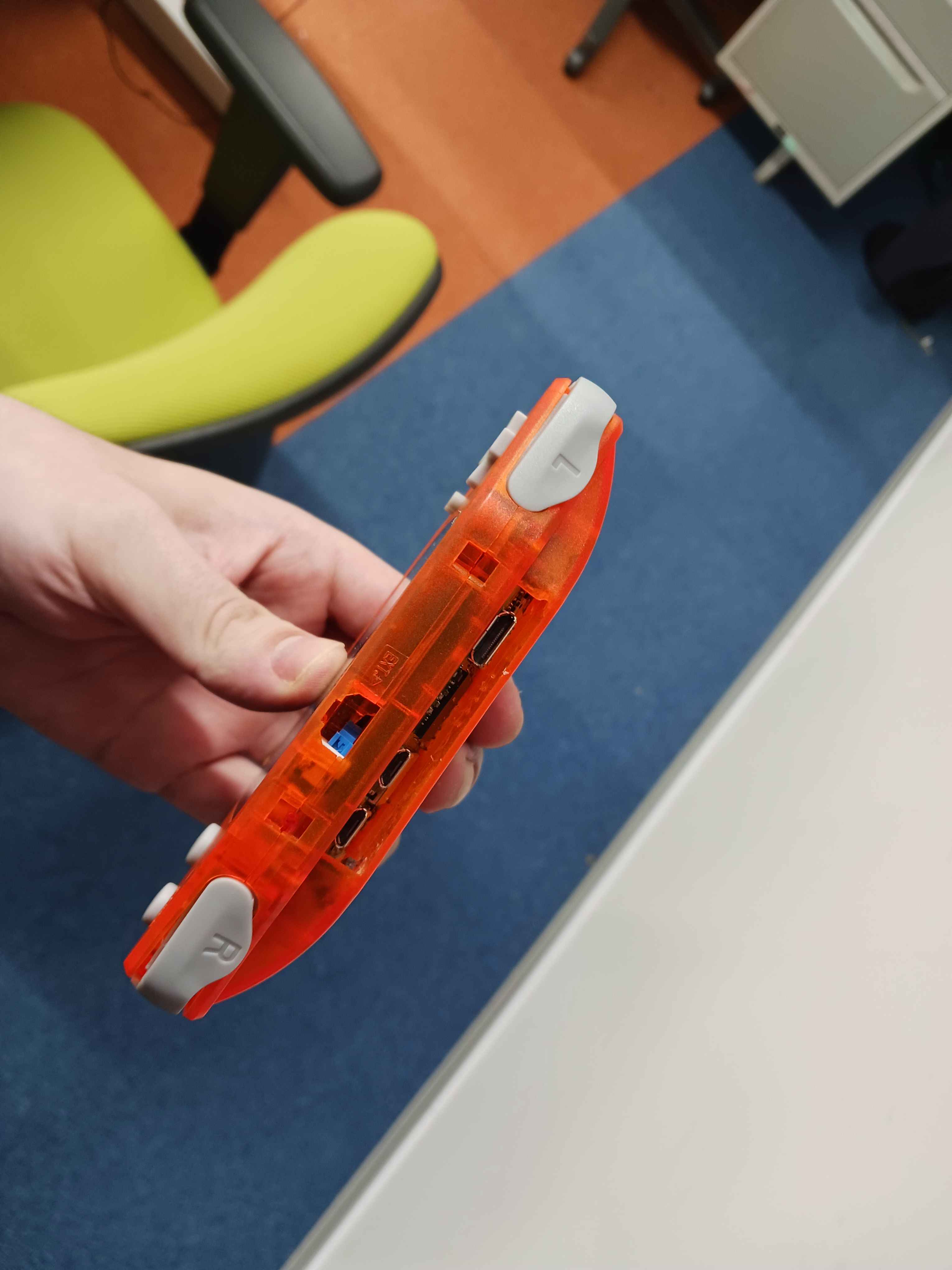
Input is handled via GPIOnext, which maps GPIO pins to gamepad buttons and exposes them as a standard input device to RetroPie. The GBA shell uses original-style button PCBs: D-pad on the left, A/B on the right, L/R on top which I wired directly to the GPIO header through a breadboard during prototyping. I also tested a Pro Controller connected via bluetooth. It worked without additional configuration, just a bit of try and error to pair. GPIOnext handles the native GPIO buttons for the final build.
Audio
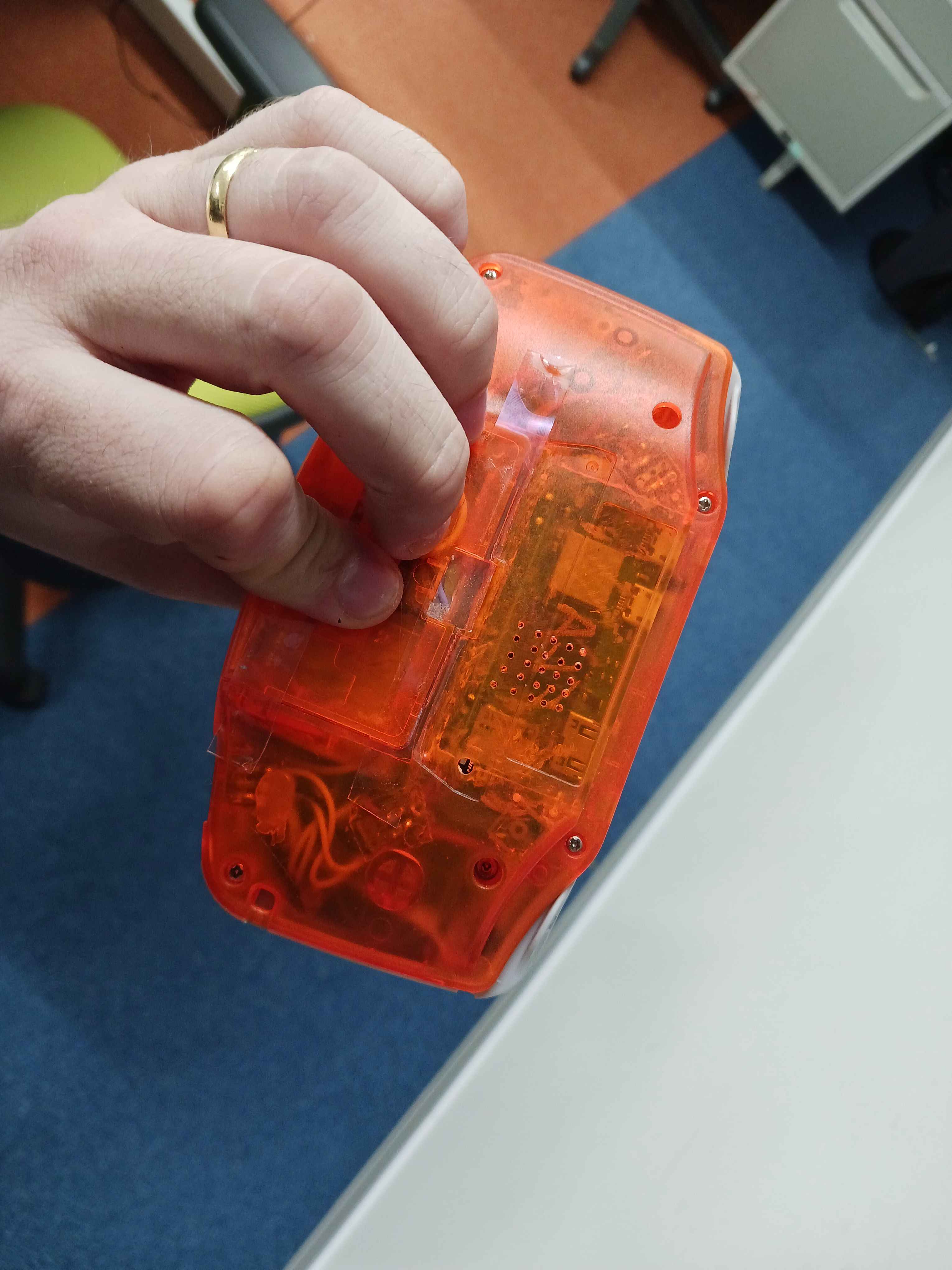
Audio is handled by a PAM8302A amplifier, which takes the Pi's PWM audio output and drives a small speaker (The original GBA one, it's not THAT good). On the Raspberry Pi Zero 2W, audio output through GPIO requires enabling the pwm and setting the right pin! The PAM8302A is compact enough to fit inside the GBA shell alongside the other components. There is also a headphone jack! This jack switches keys if you put a headphone inside, so either you hear audio from the headphone or the speakers! Not going to lie, pretty proud of this. I soldered right and left sizes of the headphone jack, since I my audio is mono.
Battery
There are three main components for the battery. The first one is the Li-Po Battery itself, of course! The next one is the battery charger and the third one is a Boost converter. The battery chargers is needed to deal with...charging the battery! It's very convenient that comes with an USB-C port and deals with the battery protection. This is not enought though. The battery gives 3.7V and Pi needs 5V. So for this we use a DC-DC Boost converter to get the 5V we need. In the project there's a switch button connected between the output of the battery charger module and the input of the boost converter. This is a way to cut the battery from the rest of the circuit if we need it. And that's it!
Assembly
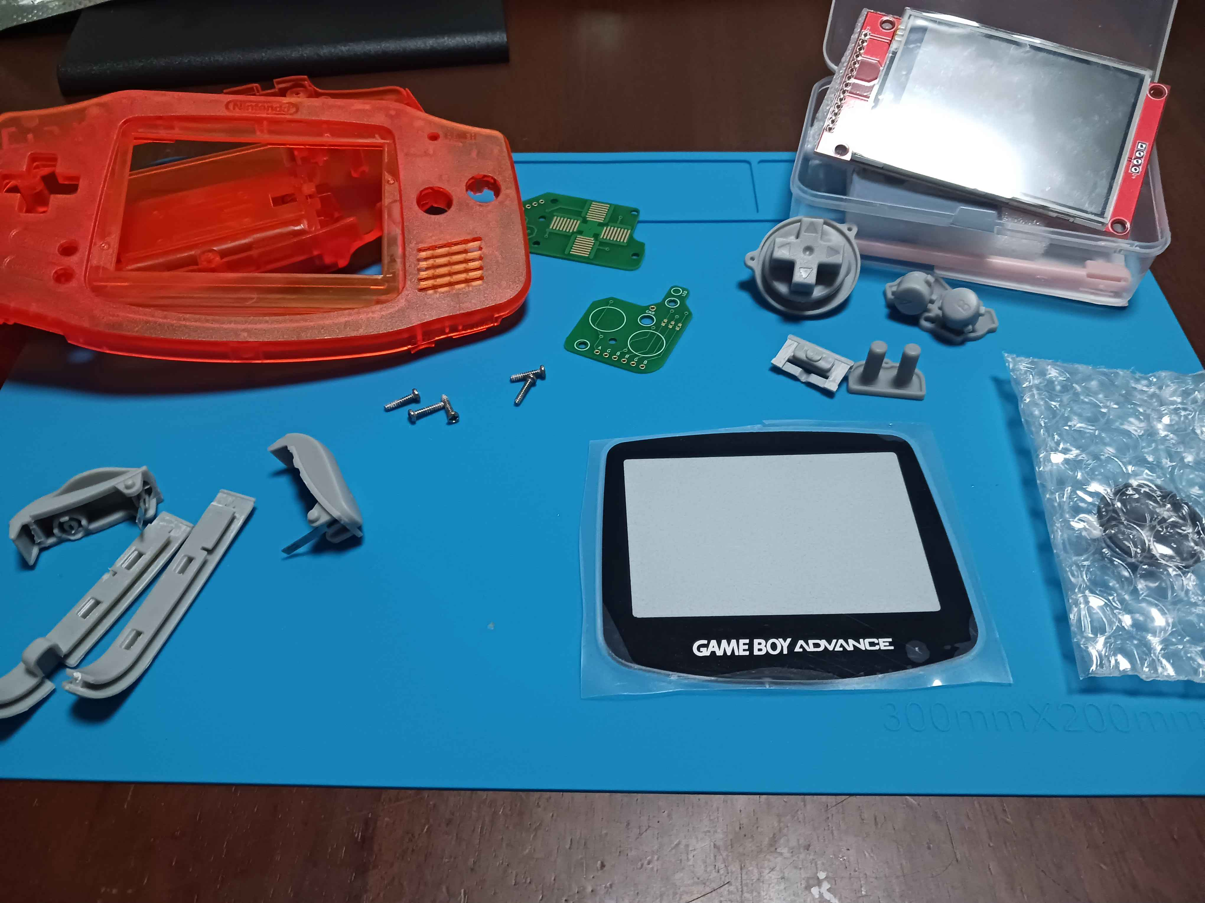
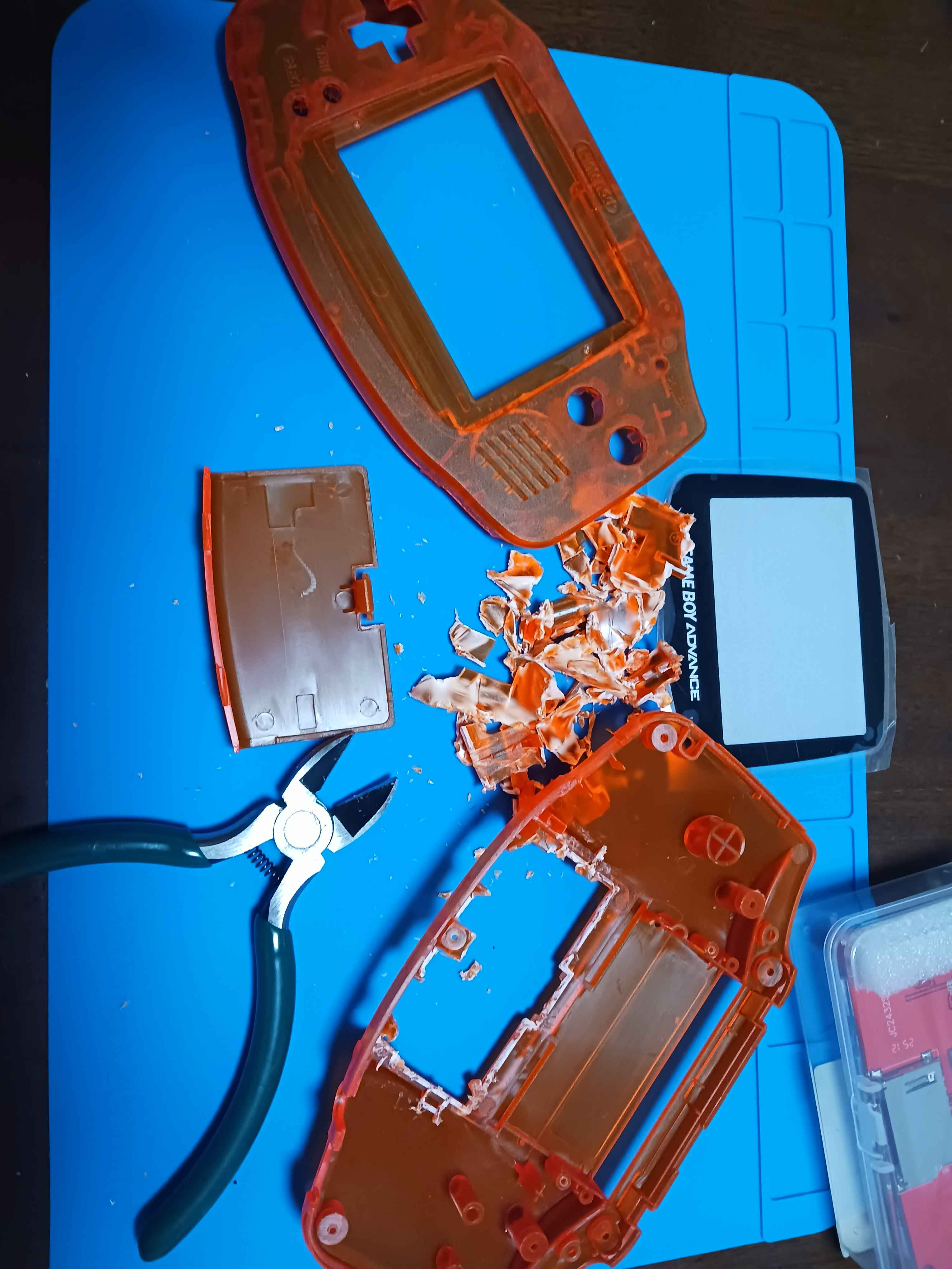
The GBA shell required physical modification to fit the hardware pieces. The original PCB mount points and battery compartment don't accommodate the Pi Zero 2W or the display PCB, so I removed material from the inside of the shell with hand tools to make room. The display window also needed adjustment to align with the ST7789 panel. The button PCBs from a GBA replacement kit connect to the GPIO header. Left side handles the D-pad, right side handles A,B, Start and Select. L and R are wired as separate tactile switches. Also, there's a led connected to a GPIO that I manage to grab the behavior of pi's own led. You see, the led of my pi stopped working while I was desoldering the pins...and this was a cool way to have a light shine when the game is on.
Another thing is the power switch. You know about the battery switch, but I didn't feel comfortable with turning of the pi by just cutting the power. I knew the pi has a GPIO that can be used to wake it up once it's "asleep", but I needed one to actually put it to sleep! So what I did is use a three point switch where the center point is GND, one point is GPIO3 and the other GPIO4. The switch is on when it's on position GPIO3: It wakes up the pi! The switch is off when it's on position GPIO4: It shuts the pi down! "Noice"! Of course, you'd still need to press the battery switch if you want save energy.
Anyhow, assembling was tought! I used AWG30 cables for data (like display cables, button signals...) and AWG24 for power cables (battery power circuit, VCC and GND of other components). I admit it. I should have put more effort in organizing the cables so they fit with less pressure then they did. It's a lesson that I'll take to the next one. If I use this amount of cables, that is. Hopefully will use a custom PCB next time.
So, what is running?
With display, input, and audio working, the system runs:
- RetroPie — the main OS and emulation frontend
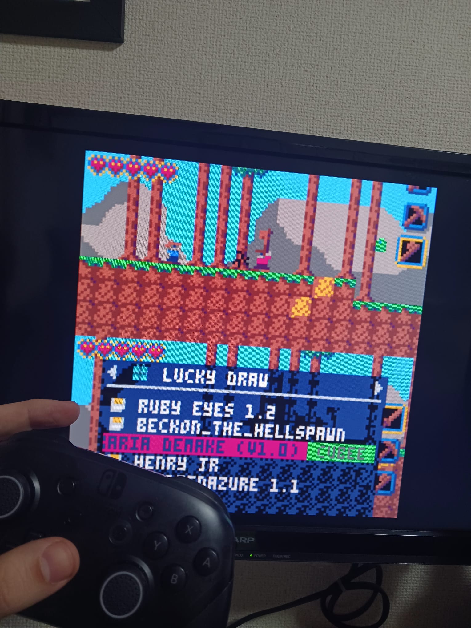
- PICO-8 — integrated as a RetroPie system; plays all PICO-8 cartridges
- Steam Link — tested and working via command line; frontend integration still in progress
Final thoughts
It works! Cable management could have been better. Lesson learned for the next build. A custom PCB would make a huge difference. If you're attempting something similar, budget extra time for the shell modifications; that's where most surprises happen! Also, planning. A lot of times I'd need to standby because I needed to wait for components or tools arrive from amazon/ali express. Sometimes there's not a lot we can do, surprises happen. But I think some could be avoided if I simply made the electrical diagram earlier, for example.
For simplicity the screen backlight is plugged in VCC. This is not really good for the device's autonomy. Because even if the pi is sleeping, the backlight would still be draining that current...well. At least I have a button to disconnect the battery. But for next time it'd be good to have a logic circuit that turns off things that don't need to be turned on. I thought on using transistors here, but I don't think I have enough space now.