Custom GBA Handheld
2026-05-13
Status: In progress — display, audio, and input working. Final assembly underway.
I really like handheld stuff! Me and my wife are always in the same ambient doing our stuff. Be it work or our hobbies. You have no idea how many monsters were hunted in monster hunter rise in my OLED switch in its handheld mode! Althought I really like my switch and still want to buy myself a steamdeck, I think they're both too big to carry around. Another thing is that I wanted a device that not only could fit in my pocket but also could run my and other pico8 games that I like! I never had a Game Boy Advance, so I thought, hey, why not?! I do like electronics, and buying one ready felt less interesting than building one. I could unite both of my interests: GameDev and Electronics!
The challenge: fitting a raspberry pi, a 2.8inch display, GPIO input handling, an audio amplifier inside a shell designed for 2001 hardware without the original PCB, without a kit, just components wired together! Oh yes, there's also the battery! This is my progress so far:
System
| Component | Part |
|---|---|
| Computer | Raspberry Pi Zero 2 W |
| OS | RetroPie |
| Display (Driver) | ST7789 2.8" SPI TFT (fbcp-ili9341) |
| Input | GPIOnext (GPIO buttons) |
| Audio | PAM8302A amplifier |
| Shell | Original GBA case (modified) |
| Battery | 2000mAh Li-Po |
| Battery Charger | Mini 18650 TP4056 Lithium Battery Charger |
| DC-DC Converter | Boost Power Supply Module (winova) |
Display
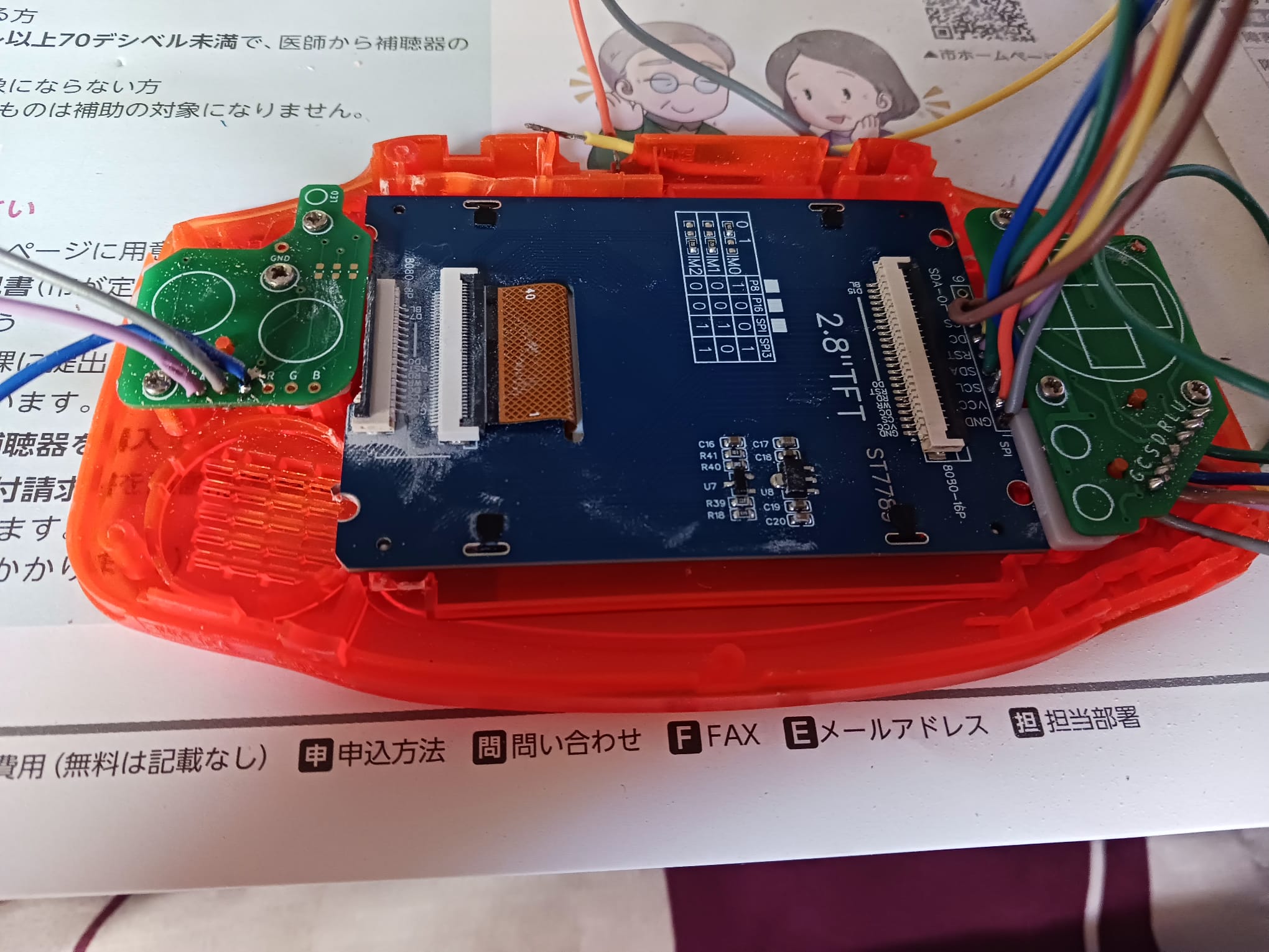
The first display I tried was an ILI9341. It worked! I got RetroPie running on it and was able to play Celeste on PICO-8. But the screen cracked while I was trying to adapt it do the GBA shell since it didn't fit cleanly inside even with physical modifications to the case. I replaced it with a ST7789 2.8" TFT, which fit the shell window much better.
Both displays use the same driver: fbcp-ili9341. Setting it up requires compiling from source with the correct GPIO pin mappings for the specific wiring. The BCM pin numbering used by the driver doesn't match the physical pin numbers on the header, which caused some initial confusion. One issue I hit: after compilation the display was showing inverted colors. Looking at the driver's documentation, this is a known quirk for certain panels and is handled by a compile flag. My final cmake command was:
cmake -DST7789=ON -DGPIO_TFT_DATA_CONTROL=24 -DGPIO_TFT_RESET_PIN=25 -DSPI_BUS_CLOCK_DIVISOR=8 -DDISPLAY_INVERT_COLORS=ON -DSTATISTICS=0 ..
Another thing I had to deal is due to how the display fit inside the shell I had to invert its image inside raspberry's boot config. This line inside the archive solved it:
display_rotate=2
Input
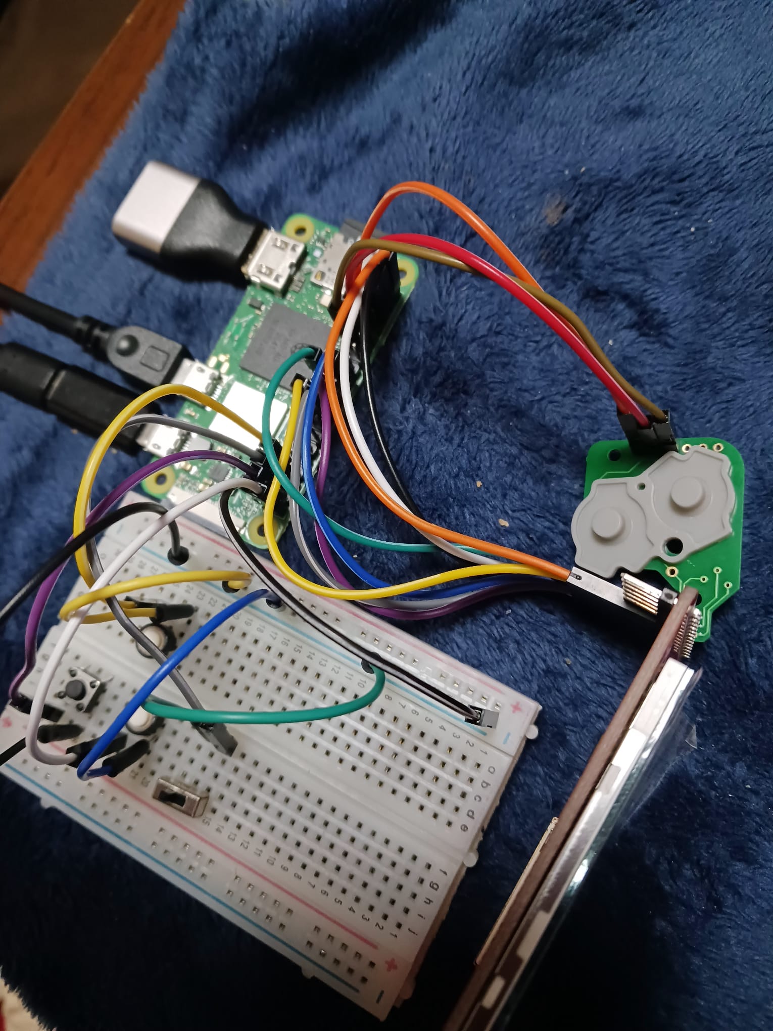
Input is handled via GPIOnext, which maps GPIO pins to gamepad buttons and exposes them as a standard input device to RetroPie. The GBA shell uses original-style button PCBs: D-pad on the left, A/B on the right, L/R on top which I wired directly to the GPIO header through a breadboard during prototyping. I also tested a Pro Controller connected via bluetooth. It worked without additional configuration, just a bit of try and error to pair. GPIOnext handles the native GPIO buttons for the final build.
Audio
Audio is handled by a PAM8302A amplifier, which takes the Pi's PWM audio output and drives a small speaker (The original GBA one, it's not THAT good). On the Raspberry Pi Zero 2W, audio output through GPIO requires enabling the pwm and setting the right pin! The PAM8302A is compact enough to fit inside the GBA shell alongside the other components.
Assembly
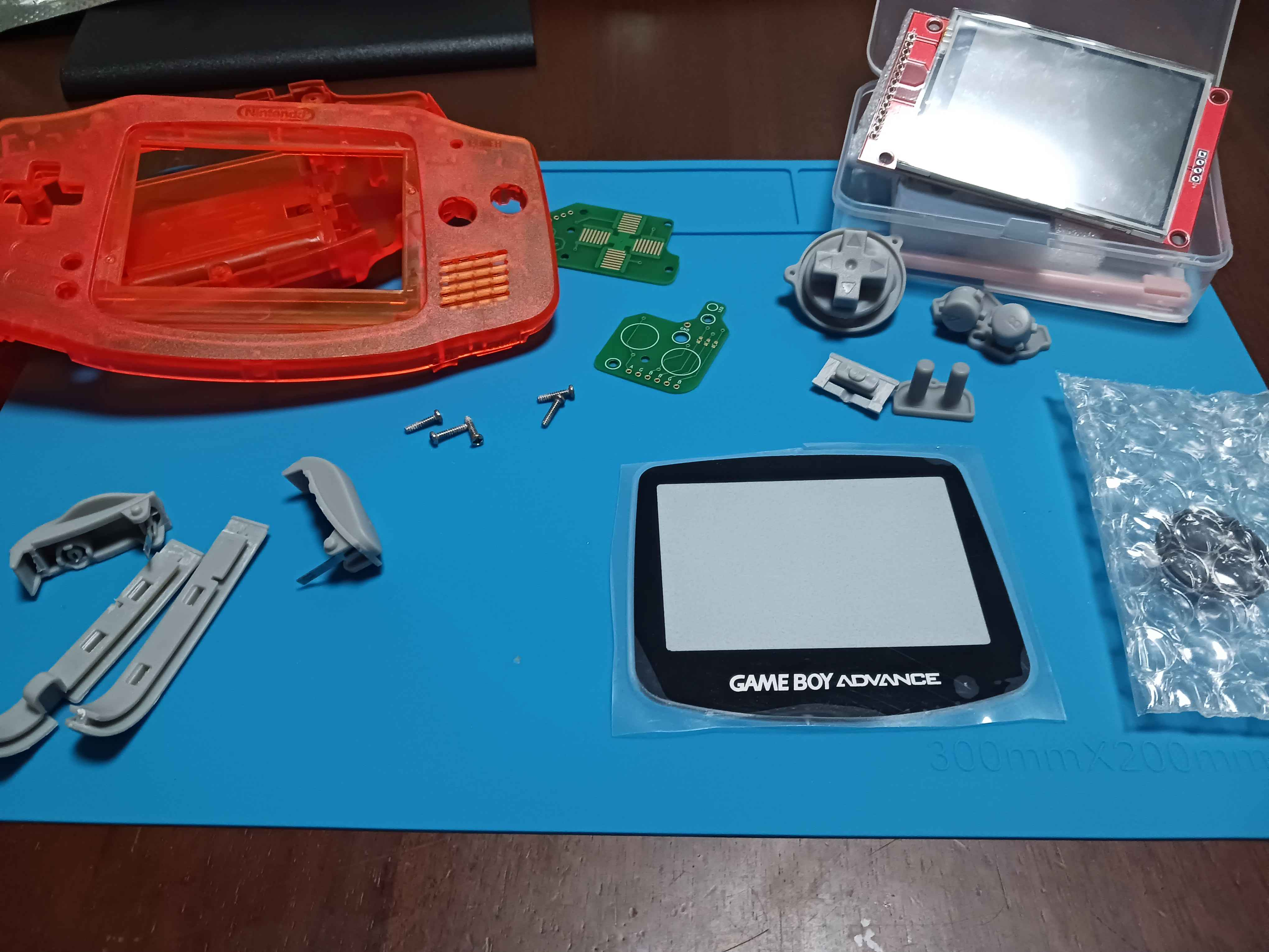
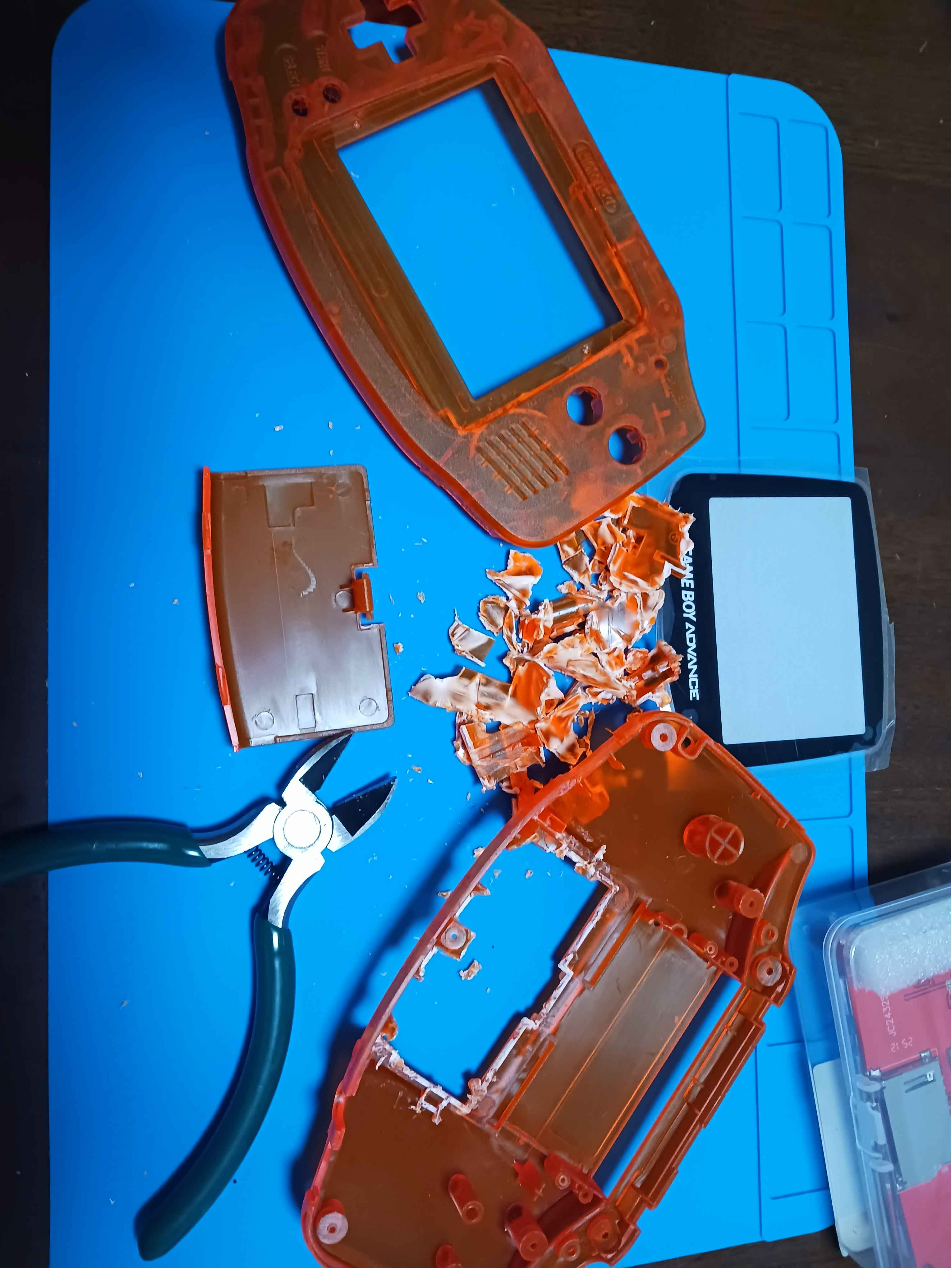
The GBA shell required physical modification to fit the hardware pieces. The original PCB mount points and battery compartment don't accommodate the Pi Zero 2W or the display PCB, so I removed material from the inside of the shell with hand tools to make room. The display window also needed adjustment to align with the ST7789 panel. The button PCBs from a GBA replacement kit connect to the GPIO header. Left side handles the D-pad, right side handles A,B, Start and Select. L and R are wired as separate tactile switches.
What is running?
With display, input, and audio working, the system runs:
- RetroPie — the main OS and emulation frontend
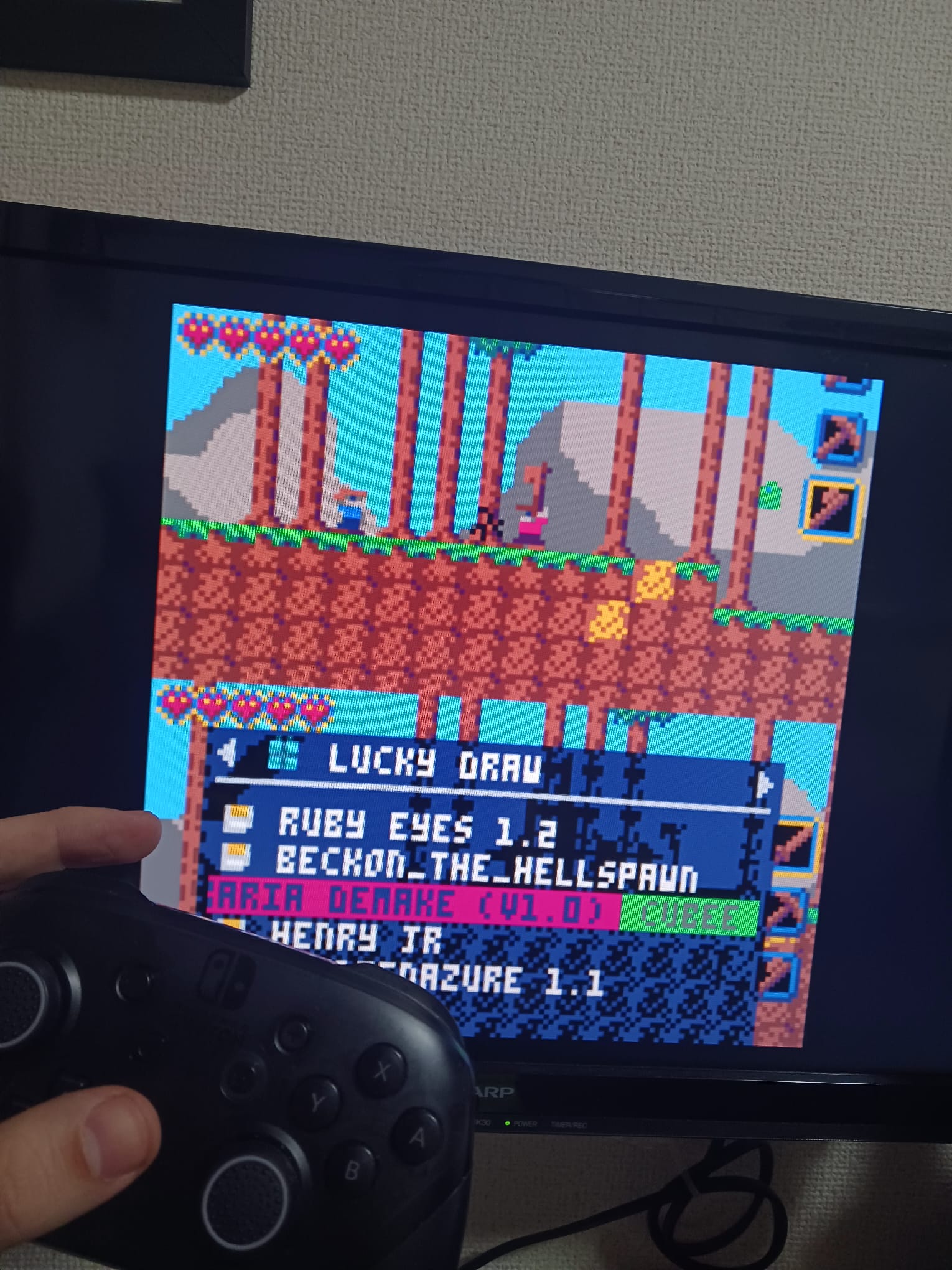
- PICO-8 — integrated as a RetroPie system; plays all PICO-8 cartridges
- Steam Link — tested and working via command line; frontend integration still in progress
What's next?
- Re-test sound system before soldering cabes
- Final soldering — moving everything from breadboard to permanent connections
- Fitting the Pi, amplifier, and speaker inside the shell with the battery
- Power management: The power button must schedules the pi to turn off and not just disconnect the battery as this might corrupt the SD card with the OS.
- Two button solution: One to turn the pi off and a hidden one that disconnects the pi
- Steam Link frontend integration so it launches from the RetroPie menu